How to read transistor, and understand it.
The triode has two working states: static and dynamic. When no signal is applied, the DC working state of the transistor is called static, and the current of each pole is called static current. The working current after adding the AC signal to the transistor is called dynamic working current. At this time, the transistor is in AC working state, that is, dynamic.
A complete triode circuit analysis has four steps: DC circuit analysis, AC circuit analysis, component and repair identification.
1, DC circuit analysis method
The direct current working voltage is applied to each electrode of the triode through two direct current circuits: one is a direct current circuit between the triode collector and the emitter, and the other is a base direct current circuit.
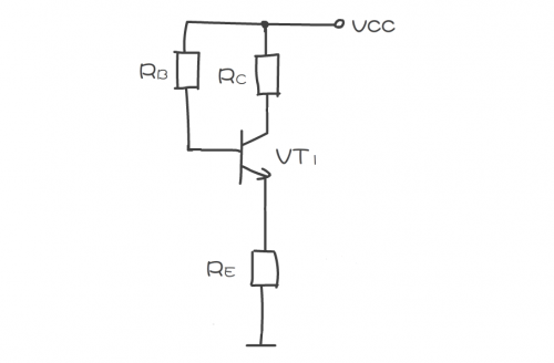
Through this step analysis, you can understand how the DC working voltage is applied to the collector, base, and emitter. As shown in the figure, it is a schematic diagram of the amplifier's DC circuit analysis. For a single-stage amplifier, its DC circuit analysis is mainly three parts shown in the figure.

When analyzing the triode DC circuit, because the capacitors in the circuit have DC blocking characteristics, they can be regarded as open circuits, so that the circuit shown in the figure above can be drawn as the DC equivalent circuit shown in the figure below, and then use this equivalent The analysis of the DC circuit is quite simple.

2, AC circuit analysis method
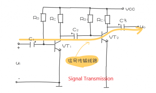
The analysis of the AC circuit is mainly the analysis of the transmission path of the AC signal, that is, where the signal is input into the amplifier, what components the signal passes through in this amplifier, and where the signal is finally output. As shown in the figure, it is a schematic diagram of the analysis of the AC signal transmission route.

It is also necessary to analyze what processing the signal undergoes during the transmission process, such as at which link the signal is amplified, at which link is attenuated, which link is not amplified or attenuated, and whether the signal is compensated.
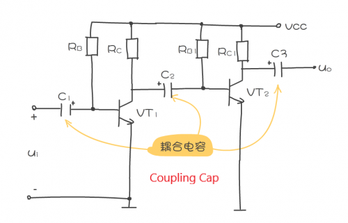
The signals in the circuit above pass through C1, VT1, C2, VT2, and C3. Among them, C1, C2, and C3 are coupling capacitors. They do not amplify and attenuate the signal, but only play a coupling role in transmitting the signal to the lower-level circuit. VT1 and VT2 amplify the signal.
3, the role of component analysis methods
1. Component characteristics are the key to circuit analysis
When analyzing the role of components in the circuit, it should be based on the main characteristics of the component. For example, the coupling capacitor allows the AC signal to pass through without loss, and at the same time cut off the DC path. The theory of this analysis is based on the capacitor's straight-through AC characteristics.
2. The specific role of components in the circuit
Each component in the circuit has its specific role, usually one component plays a specific role, of course, there is also a component that plays two roles in the circuit. It is required to understand the specific role of each component in the circuit in circuit analysis.
3.Simplified component analysis method
The analysis of the role of components can be simplified. After mastering the role of components in the circuit, it is not necessary to analyze each component in detail every time. For example, after understanding the role of coupling capacitors, it is not necessary to analyze every coupling capacitor. As shown in the figure, it is a schematic diagram of the coupling capacitance analysis.

4, repair map recognition method
Repairing and identifying pictures is for servicing circuit faults. This understanding of pictures requires that you fully understand the working principle of the circuit, otherwise it is meaningless. Because the fault phenomenon is clear, the repair identification during the troubleshooting process can be targeted to select the components in the circuit, without the need to analyze each component in the circuit.
During the analysis, find out the main components in the circuit, and assume that they have faults such as open circuit, short circuit, resistance increase and decrease, and analyze the impact of such failures on DC and AC circuits, so as to deduce possible root causes .
The key to repairing the map is to find the key test points in the circuit:
1.Key test points of single-stage amplifier
As shown, the single-stage amplifier is mainly the key test point of the transistor.

The key test points of the triode are used to measure the DC working voltage of the three electrodes. The collector is the first test point, followed by the base, and the third is the emitter.
2.Key test points of integrated circuits
The most important key test points of integrated circuits are the power supply pins, as well as the input signal pins and output signal pins.
5, triode base bias circuit analysis method
The triode base bias circuit analysis is the most difficult. Mastering some circuit analysis methods can facilitate the analysis of the base bias circuit.
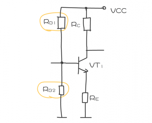
1. The first step of circuit analysis is to find the circuit symbol of the triode in the circuit, as shown in the figure, and then to find the base in the triode circuit symbol. This is a key step in analyzing the base bias circuit.
2. The second step is to start from the base and find all the components connected to the base and the power terminal. As shown in the figure, RB1 in the circuit, and then find all the components connected to the base and the ground. Such as RB2 in the circuit, these components constitute the main circuit of the base bias circuit.

Among the above components connected to the base, it is necessary to distinguish which components may be components in the bias circuit. The resistor may constitute a bias circuit, and the capacitor has a DC blocking effect and is regarded as an open circuit, so when analyzing the base DC bias circuit, the capacitor need not be considered.
3. In the third step, after determining the components in the bias circuit, analyze the base current loop, as shown in the figure. The base current loop is: DC working voltage VCC → bias resistor RB1 → VT1 base → VT1 emitter → VT1 emitter resistance RE → ground